GRASS and Blender
Externalize 3d GRASS outputs to Blender
Some GRASS GIS users are familiar with Blender 3D computer graphics software. It is a free and open-source modelling suite that provides powerful rendering/compositing/animation tools. Download Blender here.
Regarding geographic data, accessing the capabilities of such software might be very helpful to produce high quality outputs (images and complex animations), and rewarding for the data producer... but transferring digital data from GRASS to Blender is a bit tricky.
v.out.blend: really need a new add-on ?
No! All you need to manage transfers from GRASS maps to blender readable objects has already been set up, particularly v.out.ply add-on, which lets you create full-featured .ply files.
So what? finally often working between GRASS and Blender we found that most of the tasks are dealing with 3d points export, coordinates trimming, mesh creation, and image draping. Therefor v.out.blend is intended to gather these steps in one single module.
Quickly, because the syntax is very conformal to GRASS usual commands, we give a note on how to invoke v.out.blend. Afterwards we give several tips to get things to work from within Blender.
v.out.blend: usage
To run properly v.out.blend needs ParaView and its ParaView python client pvpython to be installed on your system.
v.out.blend accepts 3 arguments, first of which is mandatory :
- vinput= name of the 3d vector point to export,
- rinput= name of an optional raster map to export,
- dsn= destination folder, default is the current mapset directory (but this should not be the place to keep GRASS external files).
The add-on is region sensitive, i.e. you must care for the current region extent and resolution before running it.
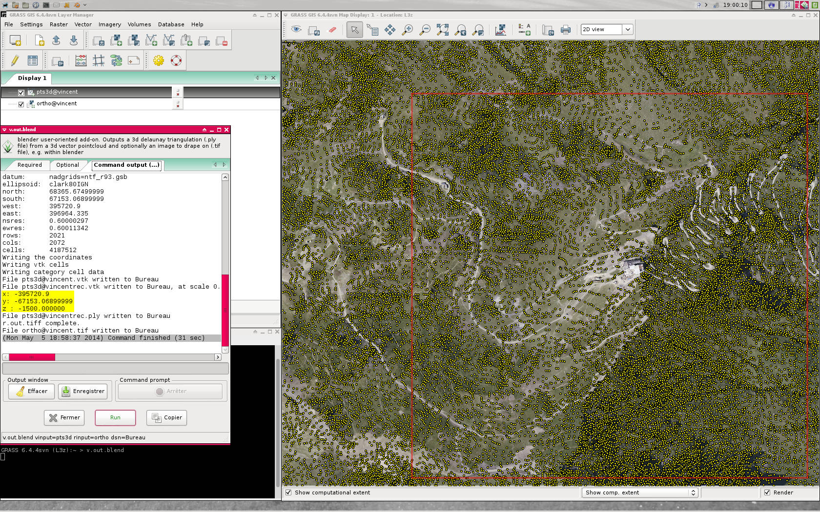
It first extracts points that fall within the region, then reciprocally adjusts the region boundaries to the newly extracted point set (this is done so that the optional raster output image fits closely to the mesh ns-ew bounds). Points coordinates may not be adapted to Blender coordinate space, so we need to apply a scale factor and shift coords to the origin. Of course one can adjust these transformation parameters to his needs by editing the add-on source code.
Points are sent to a delaunay2d filtering process, performed through pvpython. It outputs a .ply 3d mesh, warning the user about scaling and shifting made to the geometry.
The raster .tiff image is exported to the same dsn/ directory
Build the scene in Blender
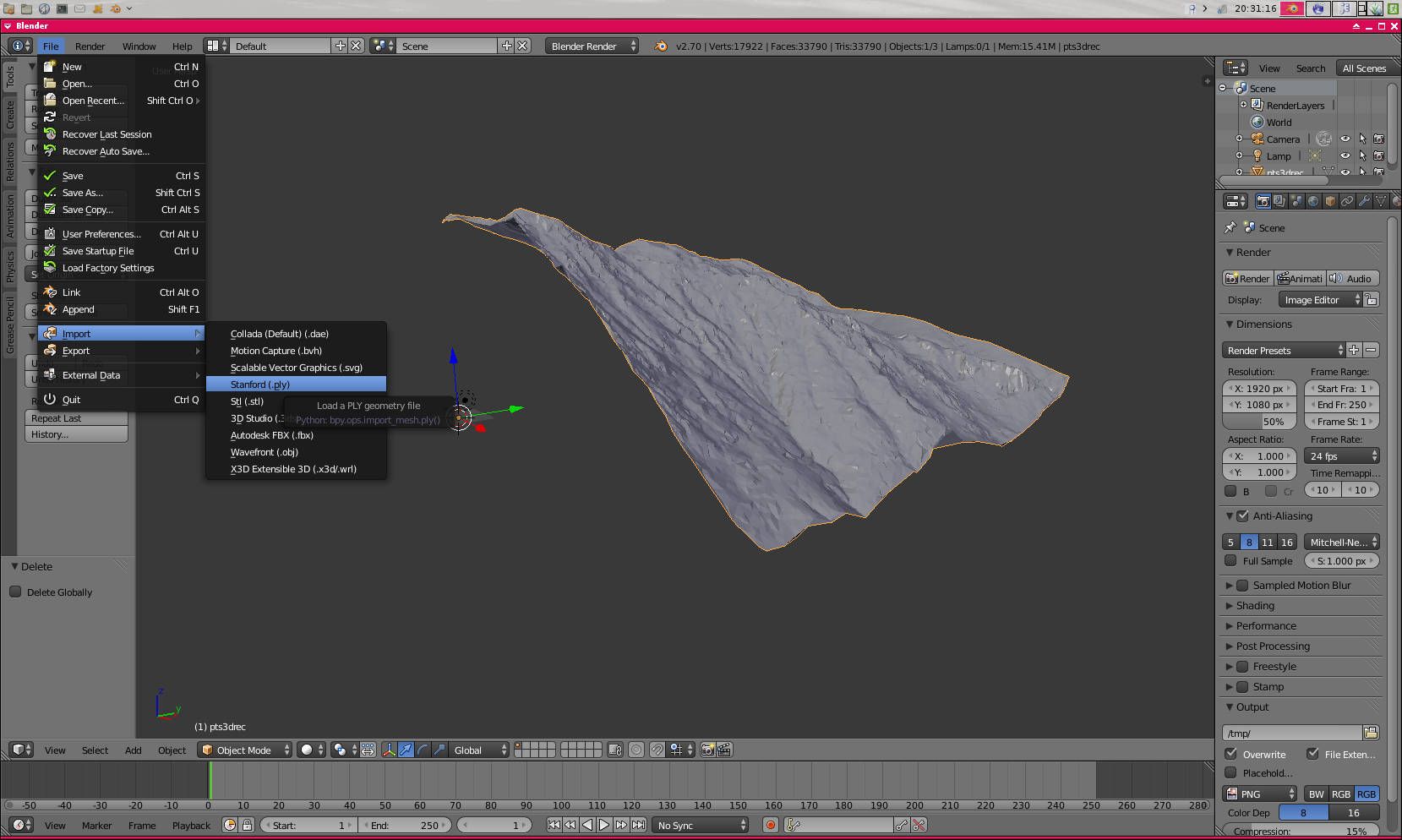
Start Blender on the default scene and import the .ply (File > Import > Stanford (.ply)).
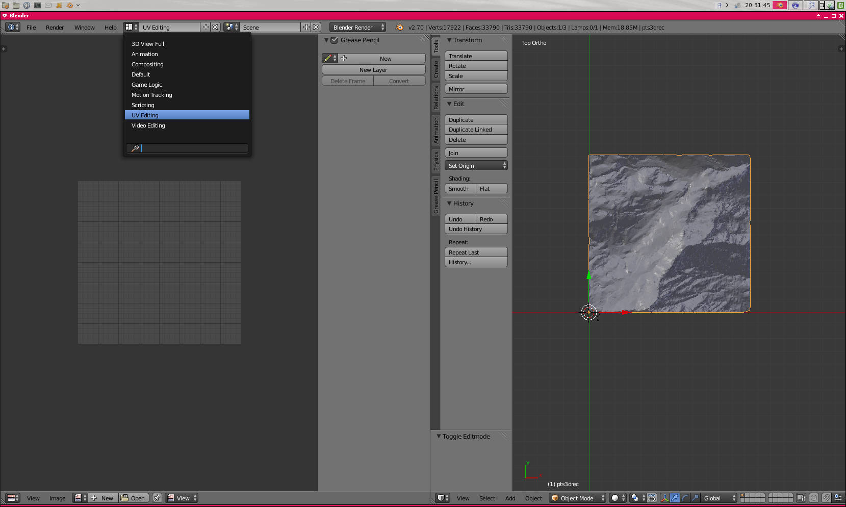
Switch to UV editing default view and set the 3d View to Top (7) and Orthographic (5).
From this view you can open the image we produced sooner ("Alt+O" or Image > Open Image).
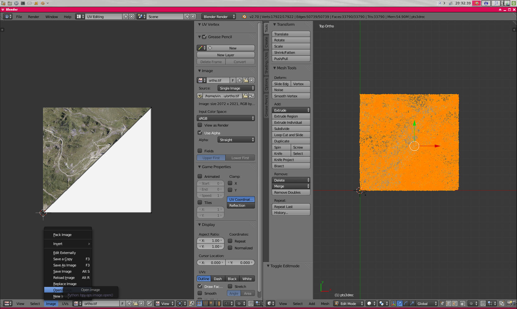
Enter the edit mode ("Tab" key), making sure all vertices are selected (by default it's ok). You just have to project the UV vertices of the mesh as they are seen i.e. from top ("U" > Projec From View(Bounds)).
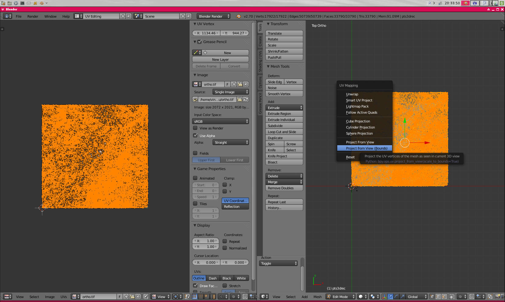
Vertices now appear in the UV editing view, Blender automatically extends the map to the dimensions of the image. You can turn back to 3d default view and assign the "Texture" method to display objects in the view. And that's it for the visualization part.
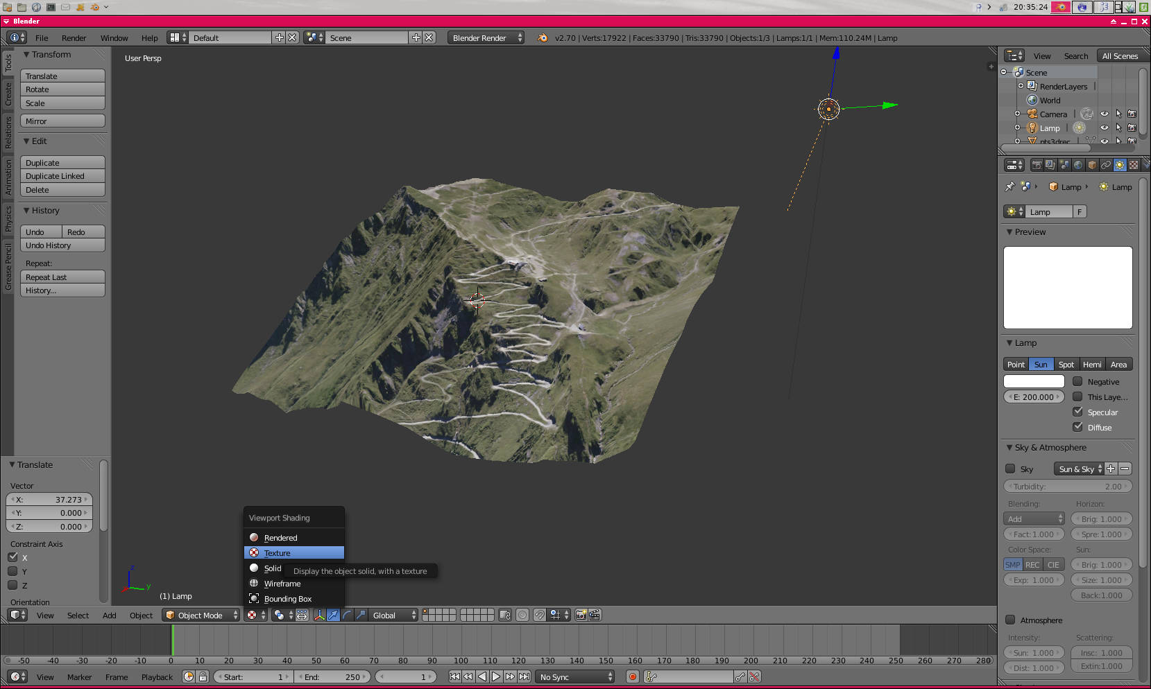
Next, to render a scene or an animation, you have to set up Texture and a Material to the mesh, but all that stuff is strictly Blender-related, and off-topic.
Enjoy !