Stereo anaglyphs: Difference between revisions
(about) |
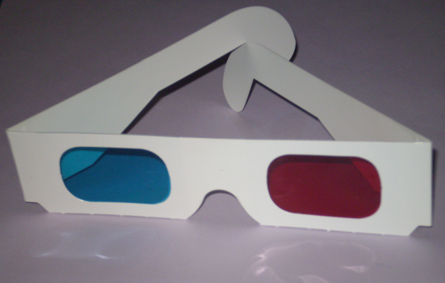
(glasses image) |
||
| Line 1: | Line 1: | ||
__TOC__ | __TOC__ | ||
[[Image:Anaglyph_glasses.png|right|150px]] | |||
An {{wikipedia|Anaglyph_3D|anaglyph}} is a 3D image created using merged offset images and viewed using red/cyan glasses. | An {{wikipedia|Anaglyph_3D|anaglyph}} is a 3D image created using merged offset images and viewed using red/cyan glasses. | ||
Revision as of 01:33, 15 June 2013

An anaglyph is a 3D image created using merged offset images and viewed using red/cyan glasses.
Module support
See the d.anaglyph addon module for an easy way to automate the process below. It uses the m.nviz.image module to render the two viewpoints, then composes the 3D image into a PNG file.

How to create stereo anaglyphs manually with NVIZ
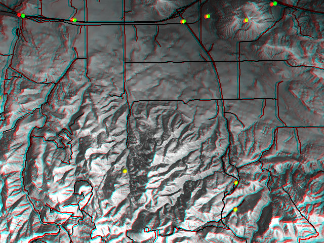
Example: http://grassold.osgeo.org/screenshots/images/mars1ana_small.jpg
Step by step
This is a quick and dirty recipe to produce red-green anaglyphs on the fly in NVIZ.
Requirements:
- You will need a pair of red-green glasses to properly watch the anaglyph image.
- Both ppmtorgb3 and rgb3toppm are required.
Note: It shouldn't be too difficult to add the core functionality as a script into NVIZ. Then we could also have animated anaglyph movies, creature-of-the-black-lagoon-style !
Recipe:
Please remember that anaglyps trade color information for depth. Consider it as a black & white image, fancy surface colors will not show.
- Load the DEM of choice into NVIZ and find a convenient viewing angle.
- Assuming your position is not tilted, move the puck a tiny bit to the left and create a PPM image (for example "left.ppm").
- Shift a bit to the right and repeat. Create another ppm image there: "right.ppm"
[It takes practice to judge the necessary distance between the viewing angles. If the completed product doesn't exactly "jump out of the screen", try again with a larger distance. Otherwise, if the final product gives you a splitting headache when looking at it, opt for a reduced distance (or something nicer to watch).] - "ppmtorgb3 left.ppm"
→ Creates from left.ppm the files left.red, left.green, left.blue - "ppmtorgb3 right.ppm"
→ Creates from right.ppm the files right.red, right.green, right.blue - "rgb3toppm left.red right.green right.blue > myfirstanaglyph.ppm"
- Put on the red-green glasses and view myfirstanagly.ppm with your favourite image viewer.
Voila !
How to create stereo anaglyphs with Paraview
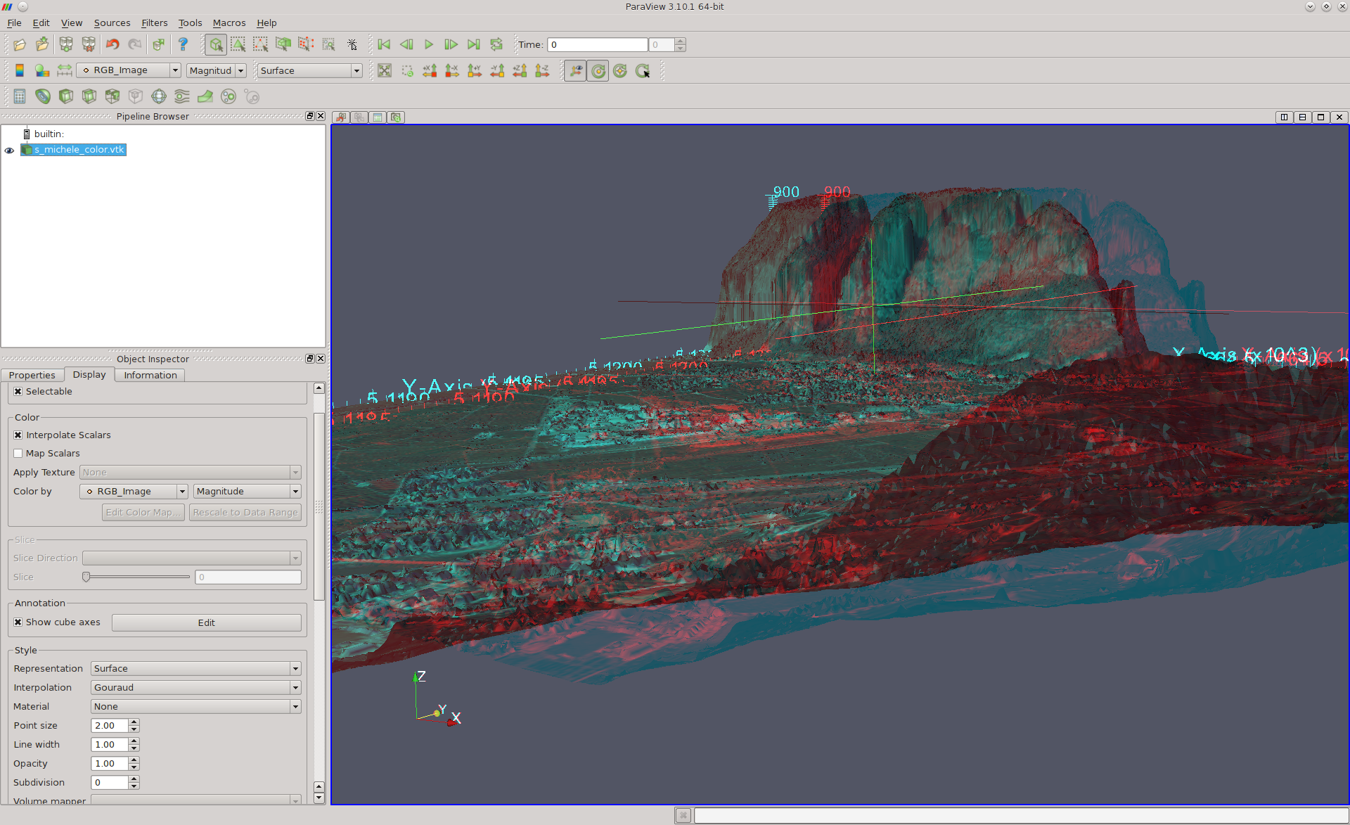
- Paraview is capable to render anaglyphs on the fly with --stereo (use r.out.vtk, r3.out.vtk, and v.out.vtk to export GRASS data to use with Paraview).
North Carolina data set example (download from http://www.grassbook.org/data_menu3rd.php):
Preparations:
  # P079215 is in PERMANENT
  # extract buildings, based on original DXF data set
  #
  v.extract in=P079215 out=bldg_resid where="layer='BLDG_RESID_BL'"
  v.extract in=P079215 out=bldg_cmcl  where="layer='BLDG_COMMER_BL'"
  # add height of the buildings
  v.extrude -t in=bldg_resid out=bldg_resid_3d elev=el_D792_6m height=10
  v.extrude -t in=bldg_cmcl  out=bldg_cmcl_3d  elev=el_D792_6m height=15
Take a look:
  g.region rast=elev_lid792_1m
  nviz elev_lid792_1m col=ortho_2001_t792_1m vect=bldg_resid_3d,bldg_cmcl_3d
Export to VTK format for Paraview:
  r.out.vtk ortho_2001_t792_1m out=ortho_2001_t792_1m.vtk elevation=elev_lid792_1m
  v.out.vtk bldg_resid_3d out=bldg_resid_3d.vt
  v.out.vtk bldg_cmcl_3d out=bldg_cmcl_3d.vtk
Normal view:
  paraview --data=ortho_2001_t792_1m.vtk
     # now load via menu:
     #   - bldg_resid_3d.vtk
     #   - bldg_cmcl_3d.vtk
Stereo view (put on the red-blue glasses):
  paraview --stereo --data=ortho_2001_t792_1m.vtk
     # now load via menu:
     #   - bldg_resid_3d.vtk
     #   - bldg_cmcl_3d.vtk

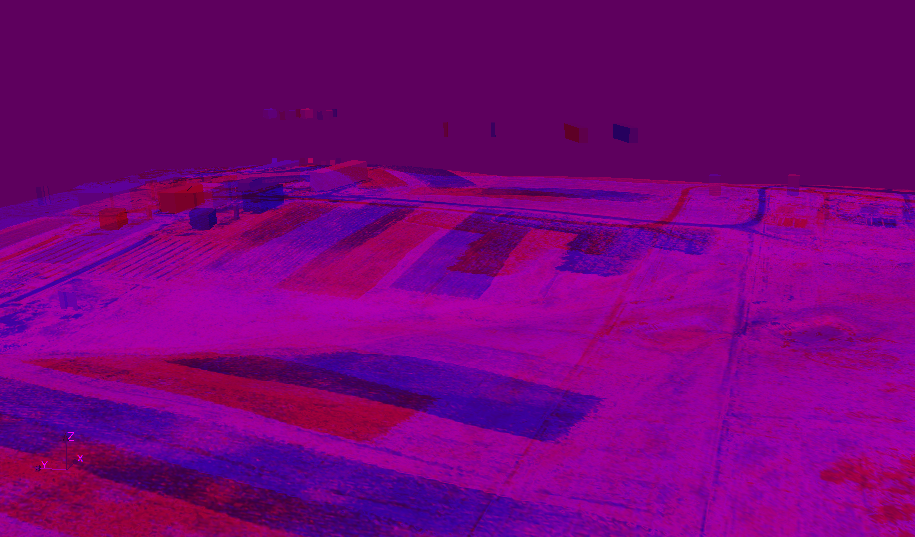
RGB stereo example (see GRASS and Paraview for details):
